Spatial Manager™ for ZWCAD - FAQs: Data Structure Management ("Standard" and "Professional" editions only)
![]()
![]()
Notes:
- Some components in the images on this page (providers, names, windows look, etc.) may be slightly different from those that will appear on your computer
- Some application functions need to access the Internet from the application itself. If you experiment problems in any process, ask your network administrator if there is a Proxy server installed on your network. You can configure the Proxy settings through the application options
- Some geographic data providers (Geocode, image Maps, etc.) may need a user account, which you can configure in the Service Provider API Keys settings through the application options
Introduction
- Objective of this section
- To learn how to define data tables and how to attach the data to the entities in a ZWCAD drawing
- Topics in this section
- Data tables: create, restore, rename, edit or delete
- Create data tables from AutoCAD Map Object Data tables
- Fields in data tables: create, edit or delete. Field types
- Calculate Field values by operating with another Field values and constants
- Data grid
- Attach data to entities
- Detach data from entities
- Label entities
- Advanced entities selection
- NOTE for Imported entities: keep in mind that in the Importing processes the data tables may be automatically defined and the imported entities will be automatically attached to the data tables. All everything you read here applies to these cases
- NOTE about the performance of the selections: the selection of entities in ZWCAD may be a few slower when the "SpatialManager" palette is open, depending on the data of the entities
How can I define data tables in a drawing?
The command 'SPMDATATABLEDEFINE' of Spatial Manager™ for ZWCAD lets you create new data tables in a drawing as well as modify them. Also use this command if you need to rename and delete data tables, or import Object Data tables from AutoCAD Map drawings. You will find this command in the "Spatial Manager" ribbon, toolbar or drop-down menu
")

Table definition window
Click on the "New Table" button to create a new (empty) data table. Select a data table in the drop-down list to rename it ("Rename Table" button), delete it ("Delete Table" button) or to modify it:
- Add Field. To add a new field in the selected data table
- Name. The field name, unique in the selected data table
- Type. You can select the field type in the drop-down list: Text, Integer, Date, etc. The field type cannot be changed if you want to modify the field later
- Length. For Text type fields you can set the maximum field length. The maximum field length cannot be changed if you want to modify the field later
- Default value. The default value for this field when the corresponding data table is attached to one or more entities
- Modify Field. To edit the selected field of the selected data table (view "Add Field" above)
- Delete Fields. To delete the selected fields of the selected data table
Note: In brackets the Length of the Field (and the number of decimal places, when applicable)

Add / Modify field window
The following is the behavior of the application when you modify a data table which is already attached to one or more entities in the drawing
- Adding a field: the new field is added to all the attached entities. If a "Default value" has been defined for the field, this will be the value assigned to the field for these entities
- Modifying a field: only the name of the field (if modified) will be changed for all the attached entities
- Deleting a field: the field will be erased for all the attached entities
As you can see in the Tables selection dropdown, there is a "scan new tables..." option to retrieve data Table structures from the drawing entities. This is useful when "Copying/Cutting and Pasting" entities from one drawing to another, when saving drawings using WBLOCK, when inserting a drawing into another, etc.
If your drawing includes AutoCAD Map Object Data tables, you can convert them to 'Spatial Manager' data tables by clickng in the "Object Data" button. Optionally you can also delete the existing Object Data tables (all or converted) from the drawing. Since you can attach several tables to any entitie (see below), if there are entities linked to several AutoCAD Map Object Data tables, the required tables and attachements will be generated for each entity

How to attach a data table to one or more entities?
When you want to attach an existing data table to one or more entities in the drawing, you can execute the command 'SPMDATATABLEATTACH' of Spatial Manager™ for ZWCAD. You will find this command in the "Spatial Manager" ZWCAD ribbon, toolbar or drop-down menu
")

First, choose a data table in the list of defined data tables in the command window. Then, the attach operation can be applied to the selected entities (if any) or to a new entities selection. Note that it is possible to attach several tables to any entity, which allows you to have data organized according to different topics attached to the same entity. For example, you can attach to entities representing parcels a table containing the parcels data and another one containing the parcel owners data
How can I modify the entities data?
You can directly edit a field value (XDATA / EED Direct data edition) for one or more entities in Spatial Manager™ for ZWCAD by selecting the entity (or entities) in the drawing and typing the new value for this field in the "Properties" area of the "SpatialManager" palette. You can also delete the field content to get a null value in this field. To validate any modification, you need to press Enter or click on a different field

Notes:
- The fields whose value starts with "http" are automatically converted into active links
- Because of performance considerations, the number of entities selected for which their data are shown in the application palette is limited by the system variable PROPOBJLIMIT
Is there any way to detach the data from the entities?
Yes, you can detach any data from one or more entities by executing the command 'SPMDATATABLEDETACH' of Spatial Manager™ for ZWCAD. You will find this command in the "Spatial Manager" ZWCAD ribbon, toolbar or drop-down menu
")

The detach operation can be applied to the selected entities (if any) or to a new entities selection
WARNING: All the current data attached to the entities (if any) WILL BE LOST
Is it possible to calculate field values based on values of other fields and/or constants? ("Professional" edition only)
Yes, the command 'SPMDATACALCULATOR' of Spatial Manager™ for ZWCAD (Fields Calculator) allows you to calculate simple or complex expressions using operators and functions that can be applied to field values in a table and/or to constant values
Note: This command was introduced in the version 8 of the application, so is not available for some old ZWSOFT products'

- Source: Select the Source Table in order to apply calculations on Field values from this Table
- Expression: In the writing panel of the Fields Calculator window you can create the expression that will be applied as a calculation to a Field of the same source Table or another Table (see below). For example, in the expression that you can see in the image below, a text value will be calculated resulting from concatenating the fixed text "Ratio=" with another text that is the result of converting into text the rounding with two decimal places of the division between the values of the fields 'Area' and 'Perim'
- You can use the "Clear" button to leave the current expression blank, and the "Preview" button to preview the calculation results in tabular format
- You can type the Operators and Functions and the source table Fields or constant values to which they apply and also select them through the sections to the left of the writing panel:
- Field: To select any Field name defined in the Source Table
- Values: To select any value from a selected Field in the Source Table (you will see all values list for the selected field), or some "special" fixed values, such as "NULL"
- Operator: Arithmetic, logical, comparator or conditional Operators. Many of them can be applied to numeric values but also to text, dates, etc. For example, the "+" operator will return the sum of two numeric values, but it will also return the concatenation of two texts
- Math: Mathematical functions such as logarithmic or trigonometric expressions, rounding, square roots, etc.
- Text: Text functions, such as full or partial text replacement, convert numerical values to text, split texts, etc.
- Date: Date functions, such as hourly, daily or monthly calculations, etc.
- Geometry: Functions applicable to entity geometries, such as area calculations, elevations, etc. They will be applied to entities attached to the Source Table
- Advanced: Set of advanced functions not included in the previous sections, such as creating lists, returning values from one list based on the values of another list, etc.
- Save value in: You can set the Field where the above expression will be applied. This Field can be an existing or a new Field in the Source Table or in any other defined Table

- Notes:
- When you pass over the Operators or Functions on the left side, you can see a small help of each of them as well as an example of use
- Complex calculations are composed within parentheses and are processed from the inner parentheses to the outer parentheses. For example, in the expression that you can see in the above image, first the division between the values of the fields 'Area' and 'Perim' is calculated (/), then the rounding of the previous result to 2 decimal places is calculated (ROUND) and, finally, this result is converted into a text with the format type "0.00" (FORMAT), so that it can be concatenated to the fixed text "Ratio="
- Fixed text values or parameters, such as the text 'Ratio=' or the '0.00' parameter of the FORMAT function in the above image, must be enclosed in single quotation marks
- When you run the Fields Calculator function, the expression writing panel will display the last expression you entered during the current work session, if you had already used the function, so that you can correct any previous expression or base a new expression on the whole or part of the last expression used
- You can get more help and info about the main available Operators and Functions through the following links:
Can I view and edit the entities data in a table form? ("Professional" edition only)
Yes, the command 'SPMDATATABLEGRID' of Spatial Manager™ for ZWCAD opens the 'Data Grid' palette where you can view, edit, etc. the entities data in any table in the drawing. You can also select entities from the 'Data Grid', export the data from the tables and more

Like any ZWCAD palette, the 'Data Grid' palette can be arranged, docked, undocked, grouped, self-collapsed, etc., and resized, depending on the preferences and needs of each user or each job, by dragging its title bar, double-clicking on its title bar, etc.

- To choose the drawing data table that you want to show in the 'Data Grid', you can use the drop-down list of available tables that can be found in the palette upper left area
- You can select which table fields you want to display in the 'Data Grid' by right-clicking on any grid area
- You can move the field separation lines in the table header to change the width of the corresponding column
- A double click on this vertical line (always in the table header) will automatically adjust the corresponding column width to the dimension of the longest value in that field
- If the value of a field in a given row cannot be seen as complete due to the width of the column, placing the cursor over the corresponding cell will display a tooltip displaying the full value in that cell. The same applies to the names of the fields in the table header
- To sort the values of a column alphabetically, click on the column name in the table header. A second click will invert the sorting
- To move and sort the fields (columns) in the table you can drag the field name itself in the table header to the left or right
- If you hover the cursor in the table header over the name of a field, a tooltip with information about the properties of that field (Name, Type, Length, etc.) will be displayed (except when the incomplete name of a field is displayed as a tooltip - see above)
- The 'Data Grid' is automatically synchronized with the current drawing (ZWCAD 2018 or upper versions)
- You can select entities in the drawing in order to highlight the corresponding attached rows in the 'Data Grid'
- If the "Automatic scroll" option (palette upper right area) is activated, the rows will be automatically scrolled to show the selected entities
- You can also select rows in the 'Data Grid' in order to select the corresponding attached entities in the drawing. You can use the CTRL and SHIFT keys (alone or in combination) when you want to select multiple rows
- If the "Automatic zoom" option (palette upper right area) is activated, the drawing view will be adjusted to the selected entities extent
- Use "Zoom to selection" (right-click menu) at any time if you want to do the same thing by hand, or "Zoom to object" if you only want to zoom to the entity under the cursor in the grid when right-clicking
- If the "Automatic centering" option (palette upper right area) is activated, the drawing view will be centered on the selected entities without modifying the zoom level
- Use "Center selection" (right-click menu) at any time if you want to do the same thing by hand, or "Center object" if you only want to center the entity under the cursor in the grid when right-clicking
- As long as you are focused on the grid rows, you can use the keyboard (Up, Down, CTRL+Up, etc.) to navigate through the rows, and the SPACE key to select rows (you will see a small "tick" checked on the row header when you select it)
- Use the selection functions (buttons set on top of the palette / right-click menu) if you want to Select All entities attached to the current table, Invert the selected entities (see note below) or Deselect all selected entities
- If the "Automatic zoom" option (palette upper right area) is activated, the drawing view will be adjusted to the selected entities extent
- Use "Delete" (buttons set on top of the palette / right-click menu) to delete selected entities and their data from the drawing (see note below)
- You can find information about the number of selected entities and the total number of entities, as well as navigation buttons between the rows selected in the table, in the palette lower left area
- Under some circumstances, synchronization may be lost. To resynchronize drawing and 'Data Grid', use the "Refresh" button next to the tables dropdown (upper left area of the palette)
- For application performance reasons, sometimes a warning will be displayed to indicate that you need to manually refresh the 'Data Grid'. For example, this may happen when a very large number of entities are deleted in the drawing
- Also for performance reasons, the selection of entities may need to use the "Activate table of selected objects" button, located to the right of the previous one, in order to update the table shown in the data grid
- If this button is enabled, the table shown in the grid is not attached to any of the selected entities. Pressing it will display the table attached to the selected entity, or to one of the selected entities if there are more than one
- When the button is disabled, the table shown in the grid is the table attached to one of the selected entities, or none of the selected entities are attached to any table
- You can select entities in the drawing in order to highlight the corresponding attached rows in the 'Data Grid'
- To edit the value in a cell, simply double-click on the cell. You can also click or press ENTER on the "active" cell to edit its value. To finish the edition, press the ENTER key or the TAB key (edit next field in the same row), or select any other cell or row in the table. To cancel editing, press the ESC key
- Pressing CTRL+ENTER will allow you to assign the current value in a cell to all cells in the same column for all selected rows
- Pressing SHIFT+ENTER will allow you to assign the current value in a cell to all cells in the same column for all rows
- You can export to an ASCII file the data in the whole table or in the selected rows only by running "Export" (buttons set on top of the palette / right-click menu)
- As you will see, you can include the field names in the export process and choose the field delimiter and the extension of the exported file

- Alternatively you can copy the table information to the Windows clipboard by using "Copy" (buttons set on top of the palette / right-click menu) or by pressing CTRL+C
- The selected rows and headers (field names) will be copied in a tab-separated format, suitable for pasting into a spreadsheet, ASCII editor, etc.
- As an exception, if a field is being edited (see above), only the value of this field will be copied to the clipboard
- From the buttons set on top of the palette you can also directly access the tables main management and data related selection commands
- Select by query (SPMSELECTBYQUERY)
- Select by table (SPMSELECTBYTABLE)
- Define table (SPMDATATABLEDEFINE)
- Attach (SPMDATATABLEATTACH)
- Detach (SPMDATATABLEDETACH)
- Fields Calculator (also in the right-click menu) (SPMDATACALCULATOR)
- Notes:
- When you use grid functions that affect selected entities (Invert, Delete, etc.), the selection refers only to those entities linked to the current table. For example when Deleting, the entities selected in the current table will be deleted but not other entities selected in the drawing (if any), which will be deselected before the deletion operation
- The "Feature_ID" column in the tables indicates the ZWCAD Handle of the entity (unique and unrepeatable for each entity in the drawing). These values cannot be edited
- If a table to which entities in the drawing are attached does not appear in the table drop-down list, try to "Restore" tables as these entities may be in the drawing after copying-pasting between drawings, inserting one drawing into another, etc.
- If closed, the application will automatically open the 'Data Grid' palette the first time you import any data source that includes a data table (EED/XDATA)
How to label the entities data in the drawing?
Although some application commands allow automatic labeling of entity data as part of the process (e.g. when Importing entities), the 'SPMLABEL' command labels data values from tables attached to the entities as Texts

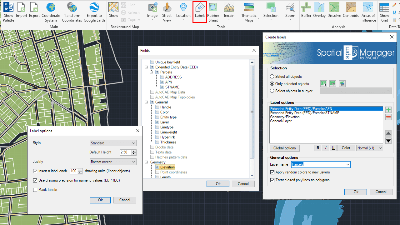
Labeling entities data in the drawing
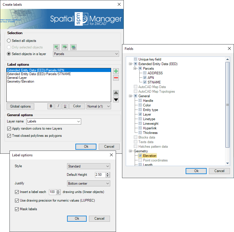
- Parameters and options
- Select all entities: all entities in the drawing will be transformed
- Only selected entities: only a selection of entities will be transformed. You can select the entities before executing this command or by using the Selecting buttons in this window
- Manual selection
- Select by Query: select entities according to the result of a simplex or compound data query (See "Selecting by Query")
- Select by Table: select entities which have been previously attached to a specific data table (See "Selecting by Table")
- Note: As you can select the entities previously to execute this command, in addition to the use of the above included selection options or in combination with them, you can make use of some other Advanced selection application tools, select entities in the Data Grid or any other selection method available in ZWCAD (Quick Select, etc.). Also note that, as most of the advanced application or ZWCAD selection commands will let you apply the selection to the current selection, the number of possible combinations to select what you are interested in is almost unlimited
- Select entities in a layer: only the entities included in a ZWCAD Layer will be transformed. You can select the layer using the drop-down list in this window
- Table and Field: Let you select the data to Label
- Warning: Please note that if none of the entities selected for labeling are attached to the chosen Table/Field, no label will be created and the application will display a warning
- Layer name: This setting defines the target Layer name for the Labels. You can select an existing Layer in the drawing or you can write the name to create a new Layer
- Apply random colors to new Layers
- Treat closed polylines as polygons: When checked (default value), all closed Polylines in the drawing will be Labeled as Polygons (Label in the Centroid). If not, these Polylines will be labeled as linear entities
- Label options. You can define the Style, Height, Justification, Rotation and Rotation Units of the Label Text entities here. Some of these parameters can be taken from Fields in the data tables. For linear entities you can also specify the separation in drawing units between labels to be repeated along the entity, or if you want a single label for each entity. As added parameters, you can set the option to use or not LUPREC for decimal places (see Notes below) and Mask labels which will generate masks (Wipeout entities, grouped with the Labels) and they will "trim" the entities located behind the Labels in order to improve its reading
- Notes:
- When Labeling, the Rotation of the Texts will consider the positive angles direction defined according to the value of the System Variable ANGDIR (Please, take a look to ANGDIR and UNITS in the ZWCAD Help)
- You can choose that the value of the LUPREC variable (Length precision) be used or not for the number of decimal places when labeling entities using a numerical field (Please, take a look to LUPREC and UNITS in the ZWCAD Help)
- Label Masks are available for ZWCAD 2020 SP2 Special Package (2020.05.15 - 56123) and upper versions
Can I graphically represent the entities data in the drawing? ("Professional" edition only)
Yes, 'Spatial Manager™ for ZWCAD' includes the 'SPMTHEMATICMAP' command which allows you to display drawing entities in different colors depending on the values of a Data Field in a table. You can read more about this functionality in the chapter dedicated to Thematic Maps
Note: This command was introduced in the version 8 of the application, so is not available for some old ZWSOFT products'
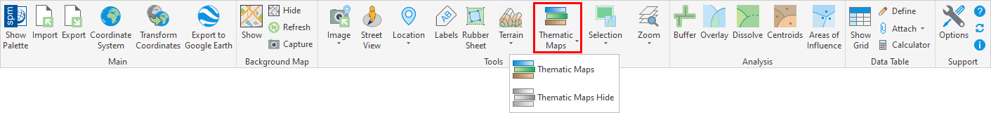
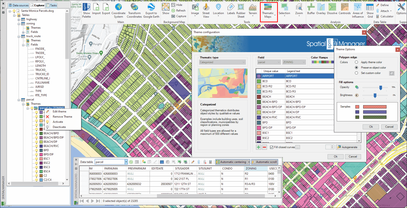
Thematic Maps in a drawing
Can I define a selection of entities based on the values of their data and/or geometries relationship?
Yes, 'Spatial Manager™ for ZWCAD' includes several commands for advanced selections tasks:

- SPMSPATIALQUERY allows you to select entities in the drawing according to the result of advanced simple or compound spatial queries
- SPMSELECTBYQUERY allows you to select entities in the drawing according to the result of a simplex or compound data query
- SPMSELECTBYTABLE allows you to select all the entities which have been previously attached to a specific data table
- SPMZOOMTOSELECTION zooms to the current selection extent so you can locate all the selected entities in an optimal size view
Related links
- Blog posts
- The new Data Grid
- Scan and recovery of data tables from drawing objects
- Geodata from ZWCAD to AutoCAD Map
- How to use Fields default value
- Create a drawing Table from the Data Grid
- Labeling existing objects
- Developed for other CAD applications prior to the release of Spatial Manager™ for ZWCAD but also applicable
![]()
![]()